TB6612 BLUE

SKU: HW-048

Power Pins

  • Vmotor – This is the voltage for the motors, not for the logic level. Keep this voltage between 4.5V and 13.5V. This power supply will get noisy so if you have a system with analog readings or RF other noise-sensitive parts, you may need to keep the power supplies seperate (or filtered!)
  • Vcc – this is the voltage for the logic levels. Set to the voltage logic you’ll be using on your microcontroller. E.g. for Arduinos, 5V is probably what you want. Can be 2.7V to 5.5V so good for 3V or 5V logic
  • GND – This is the shared logic and motor ground. All grounds are connected

Signal in Pins

These are all ‘Vcc logic level’ inputs

  • INA1, INA2 – these are the two inputs to the Motor A H-bridges
  • PWMA – this is the PWM input for the Motor A H-bridges, if you dont need PWM control, connect this to logic high.
  • INB1, INB2 – these are the two inputs to the Motor B H-bridges
  • PWMB – this is the PWM input for the Motor B H-bridges, if you dont need PWM control, connect this to logic high.
  • STBY – this is the standby pin for quickly disabling both motors, pulled up to Vcc thru a 10K resistor. Connect to ground to disable.

Motor Out Pins

These are ‘Vmotor level’ power outputs

  • Motor A – these are the two outputs for motor A, controlled by INA1, INA2 and PWMA
  • Motor B – these are the two outputs for motor B, controlled by INB1, INB2 and PWMB

17 People watching this product now!

6000 +

Products

10:00am - 7pm

Working Hours

Genuine Products

Guaranteed

Description

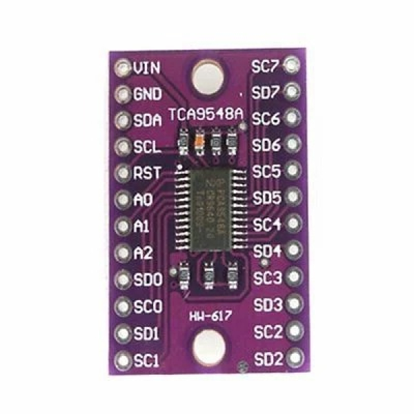
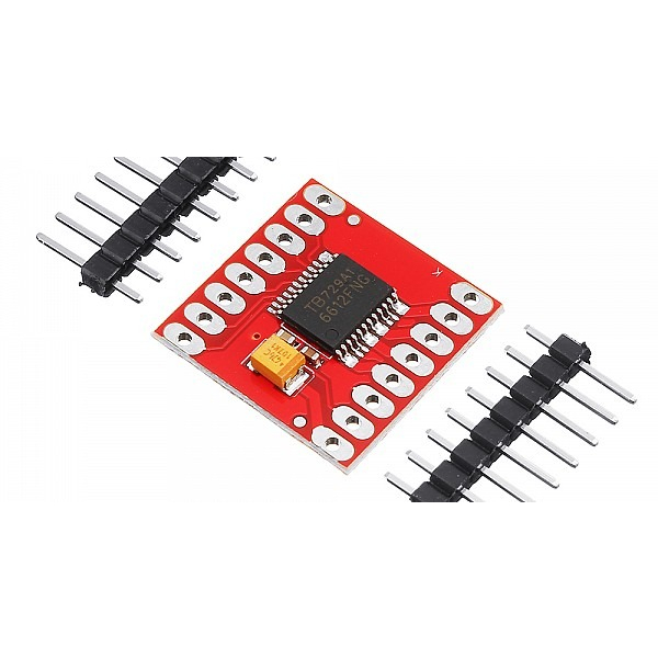
Soldered on TB6612 onto a breakout board for you here, with a polarity protection FET on the motor voltage input and a pullup on the “standby” enable pin. Each breakout chip contains two full H-bridges (four half H-bridges). That means you can drive 2-4 solenoids (only two can be active at a time, on opposite bridges), two DC motors bi-directionally, or one stepper motor. Just make sure they’re good for 1.2 Amp or less of current, since that’s the limit of this chip. They do handle a peak of 3A but that’s just for a short amount of time, like 20 milliseconds. What we like most about this particular driver is that it comes with built in kick-back diodes internally so you don’t have to worry about the inductive kick damaging your project or driver!

There’s two digital inputs per H-bridge (one for each half of the bridge) as well as a PWM input per driver so you can control motor speed. Runs at 2.7V-5V logic. The motor voltage is separate from the logic voltage. Good for motor voltages from 4.5V up to 13.5V! This wont work well for 3V motors.

Reviews (0)

Reviews

There are no reviews yet.

Be the first to review “TB6612 BLUE”

Your email address will not be published. Required fields are marked *