


| operating voltage supply |
46 v. |
|---|---|
| Power dissipation |
25W |
| Maximum input & enable voltage |
+7V |
| Storage temperature ranges |
-40°c – 150°c. |
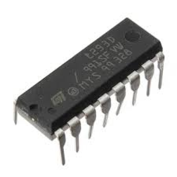
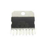
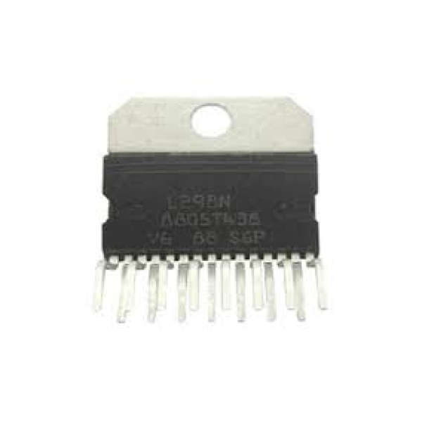
An L298 Motor Driver IC is a monolithic chip, used in motor driver modules to control the speed of a DC motor. At present, the most frequently used motor driver ICs as compared to L298 is; L293D & L2938N. This IC is frequently used in RC cars & autonomous robots. The input provided to a motor driver module is taken from a controller like Arduino.So this logic input is simply used to control the direction of the motor which is connected to the motor driver IC. The motor driver module mainly includes a motor driver IC, which is an essential component in this module. This single IC can control the motor alone but using the motor driver module by interfacing it with Arduino can make it easy. This article discusses an overview of L298 motor driver IC, working with applications.The high-power version of the L298 IC is an L293 motor driver IC. It is a dual full-bridge driver IC with high current & voltage, mainly designed to allow typical TTL logic levels to control different inductive loads like DC motors, solenoids, relays, stepper motors, etc. The motor driver is a small current amplifier that uses a low current signal to provide a high current signal for driving .
L298 IC includes four separate power amplifiers where two amplifiers can form H-bridge A and the other two types of amplifiers can form H-bridge B. Here, One H Bridge is used to switch the polarity to control the motor direction whereas pair of H bridges are used for controlling a bipolar stepper motor.


Reviews
There are no reviews yet.