IC & Transistors
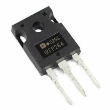
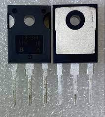
IRFP 264
- Advanced Process Technology
- Ultra-Low On-Resistance
- 175°C Operating Temperature
- Fast Switching
- Lead-Free, RoHS Compliant.
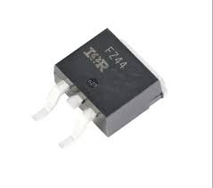
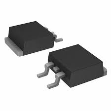
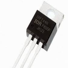
IC IRFZ44NSTRL D2PAK SMD
The IRFZ44N N-Channel Power MOSFET Transistor D2PAK Package‚ IR MOSFET family of power MOSFETs utilizes proven silicon processes offering designers a wide portfolio of devices to support various applications such as DC motors‚ inverters‚ SMPS‚ lighting‚ load switches‚ and battery-powered applications. The devices are available in various surface-mount and through-hole packages with industry-standard footprints for ease of design.
IRFB3710 MOSFET Transistor
- Part Number: IRF3710
- MAKE: Doingter
- Dynamic dv/dt Rating
- Advanced Process Technology
- Ultra Low ON-Resistance
- 175°C Operating Temperature
- Fast Switching
- Ease of Paralleling
- Simple Drive Requirements
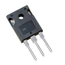
IRFP 4321
RFP4321PbF Applications l Motion Control Applications l High Efficiency Synchronous Rectification in SMPS l Uninterruptible Power Supply l Hard Switched and High Frequency Circuits Benefits l Low RDSON Reduces Losses l Low Gate Charge Improves the Switching Performance www.DataSheet4U.com l Improved Diode Recovery Improves Switching & EMI Performance l 30V Gate Voltage Rating Improves Robustness l Fully Characterized Avalanche SOA HEXFET® Power MOSFET VDSS RDS(on) typ. max. ID D 150V 12m: 15.5m: 78A D G S G D S TO-247AC D S G Gate Drain Source Absolute Maximum Ratings Symbol ID @ TC = 25°C ID @ TC = 100°C IDM PD @TC = 25°C VGS EAS (Thermally limited) TJ TSTG Parameter Continuous Drain Current, VGS @ 10V Continuous Drain Current, VGS @ 10V Pulsed Drain Current d Maximum Power Dissipation Linear Derating Factor Gate-to-Source Voltage Single Pulse Avalanche Energy e Operating Junction and Storage Temperature Range Soldering Temperature, for 10 seconds (1.6mm from case) Mounting torque, 6-32 or M3 screw Max. 78 c 55 330 310 2.0 ±30 210 -55 to + 175 300 10lbxin (1.1Nxm) Typ. ––– 0.24 ––– Max. 0.49 ––– 40 Units A W W/°C V mJ °C Thermal Resistance Parameter RθJC RθCS RθJA Junction-to-Case g Case-to-Sink, Flat, Greased Surface Junction-to-Ambient g Units °C/W www.irf.com 1 6/23/06 IRFP4321PbF Static @ TJ = 25°C (unless otherwise specified) Symbol V(BR)DSS Parameter Drain-to-Source Breakdown Voltage Min. Typ. Max. Units 150 ––– ––– 3.0 ––– ––– ––– –.
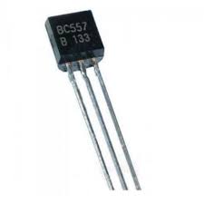
BC557-TRANSISTOR
Features:-
• Advanced process technology
• Low error voltage
• Fast switching speed
• Full-voltage operation
• High power and current handling capability
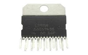
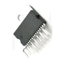
L298 Motor Driver IC
Each bridge in this IC includes two current sense pins like CSA & CSB and enable pins like ENA & ENB. Here, current sense pins are connected to the ground terminal but we can also include a low-value resistor where its voltage reading is relative to the current. Similarly, enable pins can also be used to make all the outputs active simultaneously
Pin Configuration:
The pin configurations of L298 dual full-bridge driver IC include 15-pins where each pin is discussed below. This IC includes dual bridges namely; H-bridge A & H-bridge B.
- Pin1 (Current Sensing A): This pin is used to control the flow of the current of the load.
- Pin2 & 3(Output 1 & 2): These two pins are output pins of the H- Bridge A where the current supplies throughout the load which is monitored at pin-1
- Pin4 (VS): This is a voltage supply pin, connected to +5V.
- Pin5 & 7 (Inputs): Control Inputs of the Bridge A & compatible with TTL
- Pin6 (Enable A): This is an enable input with TTL compatible
- Pin8 (GND): This is a GND pin
- Pin9 (Logic Voltage Supply): This pin provides voltage supply for the logic blocks.
- Pin10 & 12 (Inputs3 & 4): These are control inputs of bridge-B and compatible with TTL
- Pin11 (Enable B): This is an enable Input with TTL compatible
- Pins 13 & 14 (Output 3 & 4): These are output pins of the H- Bridge B where the flow of current throughout the load is monitored at pin15.
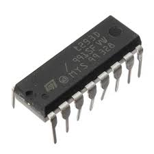
L293 - Motor Driver IC
- Motor/Logic supply 5 to 36 V
- Logic controls input 7 VDC max
- Inhibit facility/enable
- High Noise immunity
- Over temperature protection
- Capable of delivering output current up to 600 mA per channel
- The control/interface lines are accessible with Berg connector
- Header connector for motor and supply connection
- PCB dimensions 36 mm x 24 mm
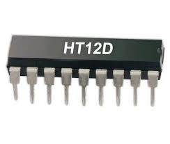
HT12D - Decoder IC
Applications of HT12D Decoder IC:-
- Burglar alarm system
- Smoke and fire alarm system
- Garage door controllers
- Car door controllers
- Car alarm system
- Security system
- Cordless telephones
- Other remote control systems
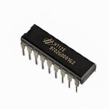
HT12E - Encoder IC
- Burglar alarm system.
- Smoke and fire alarm system.
- Garage door controllers.
- Car door controllers.
- Car alarm system.
- Security system.
- Cordless telephones.
- Other remote control systems.
